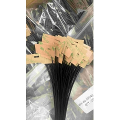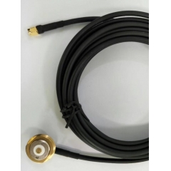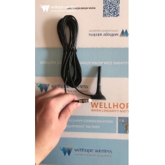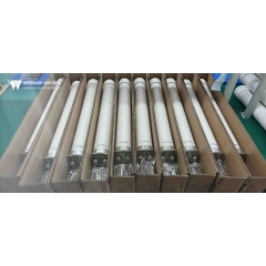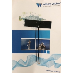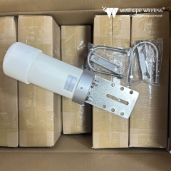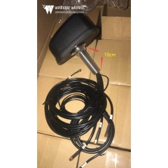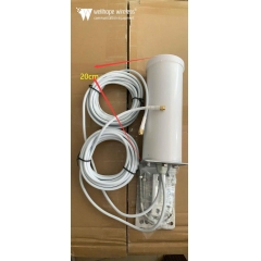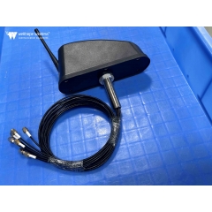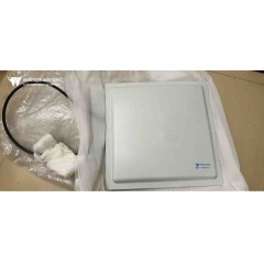

 ăng ten bộ định tuyến wifi.
Phân cực ăng-ten: Nó là gì và tại sao quan trọng
Thời gian đọc ước tính: 15 phút
Mọi kỹ sư điện tử đều biết ăng-ten truyền và nhận tín hiệu dưới dạng sóng điện từ (sóng năng lượng điện từ), với các đặc tính có thể được mô tả bằng các phương trình Maxwell. Giống như nhiều chủ đề kỹ thuật chuyên sâu khác, chúng ta có thể diễn giải các phương trình này, cùng với các quy tắc lan truyền và đặc tính của sóng điện từ, từ nhiều góc độ khác nhau—từ các mô tả định tính tương đối đơn giản đến các công thức toán học phức tạp, tinh vi.
Phân cực là một trong nhiều đặc tính của sự lan truyền năng lượng điện từ. Tác động của nó và mức độ cần được xem xét thay đổi đáng kể tùy theo các kịch bản ứng dụng khác nhau và thiết kế ăng-ten tương ứng. Các nguyên tắc cơ bản của phân cực áp dụng cho mọi bức xạ điện từ, bao gồm tín hiệu tần số vô tuyến (RF)/không dây và năng lượng ánh sáng, đồng thời phân cực được sử dụng rộng rãi trong lĩnh vực quang học. Bài viết này chỉ đề cập đến dải tần RF.
Phân cực Phân cực ăng-ten?
Để hiểu về phân cực, trước tiên cần nắm vững các kiến thức cơ bản về sóng điện từ. Một sóng điện từ bao gồm điện trường (trường E) và từ trường (trường H) truyền theo cùng một hướng. Điện trường và từ trường vuông góc với nhau, đồng thời cả hai đều vuông góc với hướng truyền của sóng phẳng.
Phân cực được định nghĩa là mặt phẳng dao động của điện trường khi quan sát từ đầu phát theo hướng truyền của sóng. Với phân cực ngang, điện trường dao động sang hai bên trong mặt phẳng ngang; với phân cực dọc, điện trường dao động lên xuống trong mặt phẳng đứng (xem Hình 1).
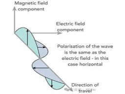
Hình 1: Sóng điện từ với các thành phần điện trường và từ trường vuông góc lẫn nhau
Các ăng-ten phát và thu tạo thành một cặp ăng-ten, và hiệu suất của bộ thu phát đạt mức cao nhất khi hai ăng-ten có cùng mặt phẳng phân cực. Gợi nhắc đến câu thoại biểu tượng trong bộ phim năm 1979 Alien—“Trong không gian, không ai có thể nghe thấy tiếng bạn hét”—không có sự khác biệt vốn có giữa phân cực ngang và phân cực dọc trong không gian vũ trụ. Dù vậy, các lý thuyết về phối hợp phân cực và căn chỉnh ăng-ten vẫn đúng để tối đa hóa việc truyền và thu năng lượng tín hiệu.
Phân cực tuyến tính và phân cực tròn
Sóng điện từ có nhiều chế độ phân cực:
- Phân cực tuyến tính cơ bản bao gồm hai dạng phân cực trực giao (vuông góc) với nhau (xem Hình 2). Về lý thuyết, một ăng-ten thu phân cực ngang không thể thu bất kỳ tín hiệu nào do một ăng-ten phát phân cực dọc phát ra ở cùng tần số, và ngược lại. Hướng phân cực của hai ăng-ten càng gần nhau thì tín hiệu thu được càng mạnh; hiệu suất truyền năng lượng tín hiệu đạt cực đại khi phân cực hoàn toàn khớp nhau.
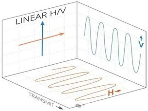
Hình 2: Phân cực tuyến tính cung cấp hai dạng phân cực trực giao với nhau
- Phân cực nghiêng là một biến thể của phân cực tuyến tính. Giống như phân cực ngang và dọc tiêu chuẩn, định nghĩa này chỉ áp dụng cho các tình huống trên mặt đất. Phân cực nghiêng tạo thành góc ±45° so với mặt phẳng ngang. Mặc dù phân cực nghiêng về bản chất là tuyến tính, khi các chuyên gia trong ngành đề cập đến “phân cực tuyến tính”, họ thường chỉ có ý nói đến các ăng-ten phân cực ngang hoặc dọc.
- Các tín hiệu được phát hoặc thu bởi ăng-ten phân cực nghiêng có thể được thu bởi ăng-ten phân cực hoàn toàn ngang hoặc dọc, mặc dù có một mức suy hao tín hiệu nhất định. Ăng-ten phân cực nghiêng lý tưởng cho các trường hợp sử dụng khi trạng thái phân cực của một hoặc cả hai ăng-ten không xác định, hoặc khi phân cực thay đổi trong quá trình hoạt động.
- Phân cực tròn (CP) phức tạp hơn phân cực tuyến tính. Ở chế độ phân cực này, vectơ điện trường liên tục quay khi tín hiệu lan truyền. Khi nhìn ra ngoài từ đầu phát, sự quay theo chiều kim đồng hồ của vectơ điện trường được gọi là Phân cực tròn tay phải (RHCP); quay ngược chiều kim đồng hồ là Phân cực tròn tay trái (LHCP) (xem Hình 3).
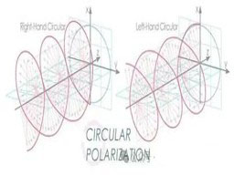
Hình 3: Vectơ điện trường của sóng điện từ phân cực tròn quay, được chia thành loại tay phải và tay trái
Tín hiệu phân cực tròn được tạo thành bằng cách chồng hai sóng điện từ trực giao có độ lệch pha 90° lên nhau. Ba tiêu chí phải được đáp ứng để tạo ra phân cực tròn: điện trường phải chứa hai thành phần trực giao; hai thành phần phải có độ lệch pha 90°; và cả hai thành phần phải có biên độ bằng nhau. Ăng-ten xoắn cung cấp giải pháp đơn giản để tạo ra sóng phân cực tròn.
- Phân cực elip (EP) là một dạng dẫn xuất của phân cực tròn. Giống như sóng phân cực tròn, sóng phân cực elip được tổng hợp từ hai sóng phân cực tuyến tính. Phân cực elip hình thành khi hai sóng phân cực tuyến tính vuông góc nhau với biên độ không bằng nhau được chồng lên nhau.
Mức độ không phù hợp phân cực giữa hai ăng-ten được định lượng bằng Hệ số suy hao phân cực (PLF), đo bằng decibel (dB). Giá trị của nó được xác định bởi góc phân cực giữa ăng-ten phát và ăng-ten thu. Về lý thuyết, PLF bằng 0 dB khi phân cực hoàn toàn phù hợp (không suy hao); nếu hai ăng-ten có phân cực hoàn toàn trực giao, PLF tiến tới vô cùng (suy giảm tín hiệu hoàn toàn).
Tuy nhiên, trong các ứng dụng thực tế, ăng-ten không thể đạt được phân cực hoàn toàn phù hợp hoặc hoàn toàn trực giao. Sai lệch khi lắp đặt cơ khí, lỗi vận hành của con người, biến dạng kênh, phản xạ đa đường và các yếu tố khác đều tạo ra độ lệch góc đối với hướng phân cực của điện trường được truyền. Ngay cả khi hai ăng-ten được thiết kế cho phân cực trực giao, hiện tượng rò rỉ phân cực chéo từ 10 đến 30 dB hoặc cao hơn vẫn xảy ra trong thực tế. Trong một số trường hợp, tín hiệu rò rỉ này đủ mạnh để gây nhiễu quá trình giải điều chế tín hiệu mong muốn.
Ngược lại, ngay cả với phân cực lý tưởng và căn chỉnh chính xác của hai ăng-ten, các yếu tố môi trường thực tế có thể khiến PLF đạt 10 dB, 20 dB hoặc cao hơn, làm suy giảm khả năng thu tín hiệu. Nói đơn giản, phân cực chéo không mong muốn và hệ số suy hao phân cực cao tạo ra hai tác động bất lợi: chúng đưa vào tín hiệu gây nhiễu và làm suy giảm cường độ của tín hiệu hữu ích mục tiêu.
Tại sao đặc tính phân cực quan trọng
Phân cực tuân theo quy tắc hai chiều: loại phân cực của hai ăng-ten càng thẳng hàng và nhất quán với nhau thì cường độ tín hiệu thu được càng cao. Ngược lại, phối hợp phân cực kém khiến cả bộ thu mục tiêu và bộ thu nhiễu khó thu đủ tín hiệu có thể sử dụng. Trong hầu hết các trường hợp, kênh không dây làm thay đổi trạng thái phân cực của tín hiệu truyền đi, hoặc một hay cả hai bộ thu phát không thể duy trì hướng ăng-ten cố định, đứng yên.
Việc lựa chọn chế độ phân cực thường được quyết định bởi môi trường lắp đặt và điều kiện lan truyền khí quyển. Ví dụ, ăng-ten phân cực ngang mang lại hiệu suất tín hiệu tốt hơn và phân cực ổn định hơn khi được lắp gần trần nhà; ngược lại, ăng-ten phân cực dọc được lắp sát tường bên thể hiện đặc tính phân cực gần với thông số thiết kế danh định hơn.
Các ăng-ten lưỡng cực thông dụng (lưỡng cực tiêu chuẩn / lưỡng cực gấp) hoạt động ở phân cực ngang khi được lắp đặt theo cách thông thường (xem Hình 4). Nếu cần phù hợp với một chế độ phân cực cụ thể, ăng-ten có thể được xoay 90° để chuyển sang phân cực dọc (xem Hình 5).
SHAPE \* MERGEFORMAT
Hình 4: Ăng-ten lưỡng cực thường được lắp theo phương ngang trên cột để tạo phân cực ngang
SHAPE \* MERGEFORMAT
Hình 5: Ăng-ten lưỡng cực có thể được lắp đặt theo phương thẳng đứng trên cột để tạo phân cực đứng khi ứng dụng yêu cầu
Phân cực đứng được sử dụng rộng rãi trong các bộ đàm cầm tay, chẳng hạn như các thiết bị do nhân viên cứu hộ khẩn cấp mang theo. Điều này là do hầu hết các ăng-ten vô tuyến phân cực đứng có đặc tính bức xạ đa hướng—nghĩa là người dùng không cần điều chỉnh lại góc phương vị của ăng-ten ngay cả khi hướng của thiết bị cầm tay liên tục thay đổi.
Hầu hết ăng-tenhoạt động trong dải Tần số Cao (HF) từ 3–30 MHz sử dụng các cấu trúc ăng-ten dây dài đơn giản được căng theo phương ngang giữa các điểm đỡ. Kích thước vật lý lớn của chúng được quyết định bởi bước sóng tương ứng (10–100 mét), và các ăng-ten như vậy vốn có phân cực ngang.
Điều thú vị là dải này được đặt tên là “Tần số Cao” cách đây nhiều thập kỷ khi 30 MHz được xem là một dải tần số cao. Mặc dù tên gọi này ngày nay có vẻ lỗi thời, nó vẫn là tên gọi dải tần chính thức do Liên minh Viễn thông Quốc tế (ITU) quy định và vẫn được sử dụng rộng rãi trên toàn thế giới.
Dải Sóng Trung (MW) trải dài từ 300 kHz đến 3 MHz. Kiểu phân cực được các đài phát sóng lựa chọn trong dải này phụ thuộc vào việc đài dựa vào sóng mặt đất để phủ sóng tín hiệu mạnh trong phạm vi ngắn hay sóng trời tầng điện ly để truyền dẫn khoảng cách xa. Nhìn chung, ăng-ten phân cực đứng cho khả năng truyền sóng mặt đất vượt trội, trong khi ăng-ten phân cực ngang phù hợp hơn cho truyền thông bằng sóng trời.
Truyền thông vệ tinh phụ thuộc nhiều vào phân cực tròn. Vệ tinh liên tục thay đổi tư thế so với các trạm mặt đất và các vệ tinh khác. Hiệu suất truyền tín hiệu đạt mức cao nhất khi cả đầu phát và đầu thu đều sử dụng ăng-ten phân cực tròn; việc ghép ăng-ten phân cực tuyến tính với ăng-ten phân cực tròn vẫn hoạt động nhưng gây ra hệ số suy hao phân cực có thể đo được.
Các đặc tính phân cực cũng cực kỳ quan trọng đối với hệ thống 5G. Một số mảng ăng-ten Nhiều Đầu vào Nhiều Đầu ra (MIMO) 5G tận dụng công nghệ phân cực để sử dụng tài nguyên phổ hiệu quả hơn, giúp tăng tốc độ thông lượng. Điều này đạt được bằng cách kết hợp các chế độ phân cực khác nhau của tín hiệu với ghép kênh không gian của ăng-ten (đa dạng không gian). Các hệ thống như vậy truyền đồng thời hai luồng dữ liệu độc lập, trong đó mỗi luồng được đưa đến các ăng-ten riêng biệt có phân cực trực giao lẫn nhau, cho phép bộ thu giải điều chế hai luồng riêng biệt. Mặc dù các yếu tố không lý tưởng bao gồm đường truyền lan truyền, biến dạng kênh, phản xạ và hiệu ứng đa đường gây ra nhiễu phân cực chéo nhỏ, bộ thu sẽ xử lý giảm thiểu vấn đề này bên trong hệ thống.
Kết luận
Phân cực là một đặc tính quan trọng nhưng thường bị bỏ qua của ăng-ten. Phân cực tuyến tính (bao gồm các biến thể phân cực ngang và đứng), phân cực nghiêng, phân cực tròn và phân cực elip đều phù hợp với các kịch bản ứng dụng khác nhau. Hướng tương đối và mức độ phối hợp của các ăng-ten ở đầu phát và đầu thu trực tiếp quyết định hiệu suất tổng thể của toàn bộ liên kết RF. Nhiều loại ăng-ten tiêu chuẩn bao phủ tất cả các kiểu phân cực và dải tần RF hiện có trên thị trường để cung cấp các giải pháp phân cực phù hợp với mọi ứng dụng mục tiêu.